
Custom Scale for the Doepfer Trautonium Manual A-198

The Trautonium is one of the oldest complete electronic musical instruments, and has been in use for almost 100 years. Just like the Ondes Martenot, the Trautonium, later the Mixtur Trautonium is simultaneously unknown and recognizably famous, though both are typically misidentified by listeners as a Theremin since all three electronic instruments are typically played in a manner that showcases their elastic glissando and vibrato effects as well as practically infinite sustain.
Dieter Doepfer created a modernized version of the Trautonium and the Mixtur Trautonium’s unique tone-generating infrastructure (linear controller, subharmonic generator, formant filters, etc.) and has published a comprehensive article on the Doepfer website that goes into detail about the original instrument and the company’s endeavor to make most aspects of it financially within reach of as many musicians as practical.
I dedicated almost an entire 3U course of my monster eurorack system to the Trautonium modules and set about trying to make music with it.
Once I got the scale and pressure sensitivity adjusted, the manual (touch controller) seemed musically intuitive and capable of expression through violin-esque finger vibrato and decently responsive pressure sensitivity to control tremolo and swells.

The linear/pressure sensor strip has two major shortcomings (and one minor one which could be just my individual unit):
1) the system is protected by a (I think) polyester film and whose smooth surface does not permit easy, repeated glissando slides with human skin.
2) the system has no inbuilt fiducial system— Most of the Trautonium manuals that I’ve seen in photos have sets of leather-clad tabs spaced along the continuum of the wire at specific note intervals, and the Doepfer manual sort of leaves this up to you— which I don’t mind at all. I like making things that don’t exist but should.
The first issue is solved by using a cotton finger cot — like the kind used by jewelers. They are made to be used for a shift or whatever and are inexpensive and disposable, mere dollars get you hundreds of them from the various bay and jungle stores online.
The resolution to the second issue is a bit more complicated and depends greatly on how the musician intends to use the controller.
At this stage of my Trautonium journey, I think I can get the most out of it as a melody-maker, and to best play melodies, I found having a wide range of pitches (4 full octaves) along the length of the manual was of the most use. The Doepfer A-198 TRC unit allowed me to set this scale, and it seems to repeat well between power cycles.
With a control surface length of about 20 inches (51 cm), the 4 octaves of notes were about 3/8” (10 mm) from center-to-center according to my tape measure. The distances between the pitches seemed consistent and persistent between power cycles, so I then tried to envision a way to have a marker system that could be installed/swapped as part of the controller.
Pianos, organs, and other keyboard instruments all have a ubiquitous system of organizing repeating pitches along a continuum, so I first considered a 20” paper card or something with the black/white piano key layout printed along its length so I’d have some visual idea of exactly which note was where on the controller. I then realized that the black keys on the keyboard were an afterthought, and that meant that the adjacent semitones of the C-major scale (b-c, e-f) were physically the same space as the whole tones (c-d, d-e, f-g, g-a, a-b), so a justified, linear control strip would never visually represent that unjust note spacing of physical keys.
I then though about how stringed instruments, though non-linear, have a system of demarcation that might more easily apply to a linear controller (as it did on the Synthaxe, with its equally-spaced ‘frets’), and as someone at-home on guitar-type instruments, this seemed like the most logical fit for my Trautonium scale.
As a proof-of-concept, I created a simple 10mm on-center row of rectangles in CAD, dropped in some marker dots in a typical pattern that repeated each octave, and printed two complete octaves twice (my printer is set up for 11” paper, so I knew 10” x 2 with some glue and a backer was how my prototype would be realized.

I cut some corrugated plastic sheeting (which I always keep on-hand for prototyping) and smeared some Titebond wood glue along the surface. I knew this wasn’t going to last, and I didn’t need it to last longer than a few trial runs to make sure my assumptions about the reliability of the position/note along the controller was sufficient to warrant a better, more permanent, more expensive build.

With my placard printed, glued, and ready to be tested, I rested it along the top edge of the controller and tested, tested, and tested some more over the course of 2 months.

I found that having the scale card able to slide from left to right along the controller continuum was helpful as there were slight pitch drifts (not the spacing of the notes, just the frequency of the median tone) and this simple ability to nudge the card a few millimeters to line up with the correct pitch was simpler, quicker, and easier than fiddling with the tiny control knob on the main oscillator throughout the session, so that feature needed to be preserved for the final version.
Overall, it worked great every time, but it needed to be a bit sturdier and look nicer— and it needed to be attached to the A-198 manual so that it wouldn’t flop over at inopportune moments.
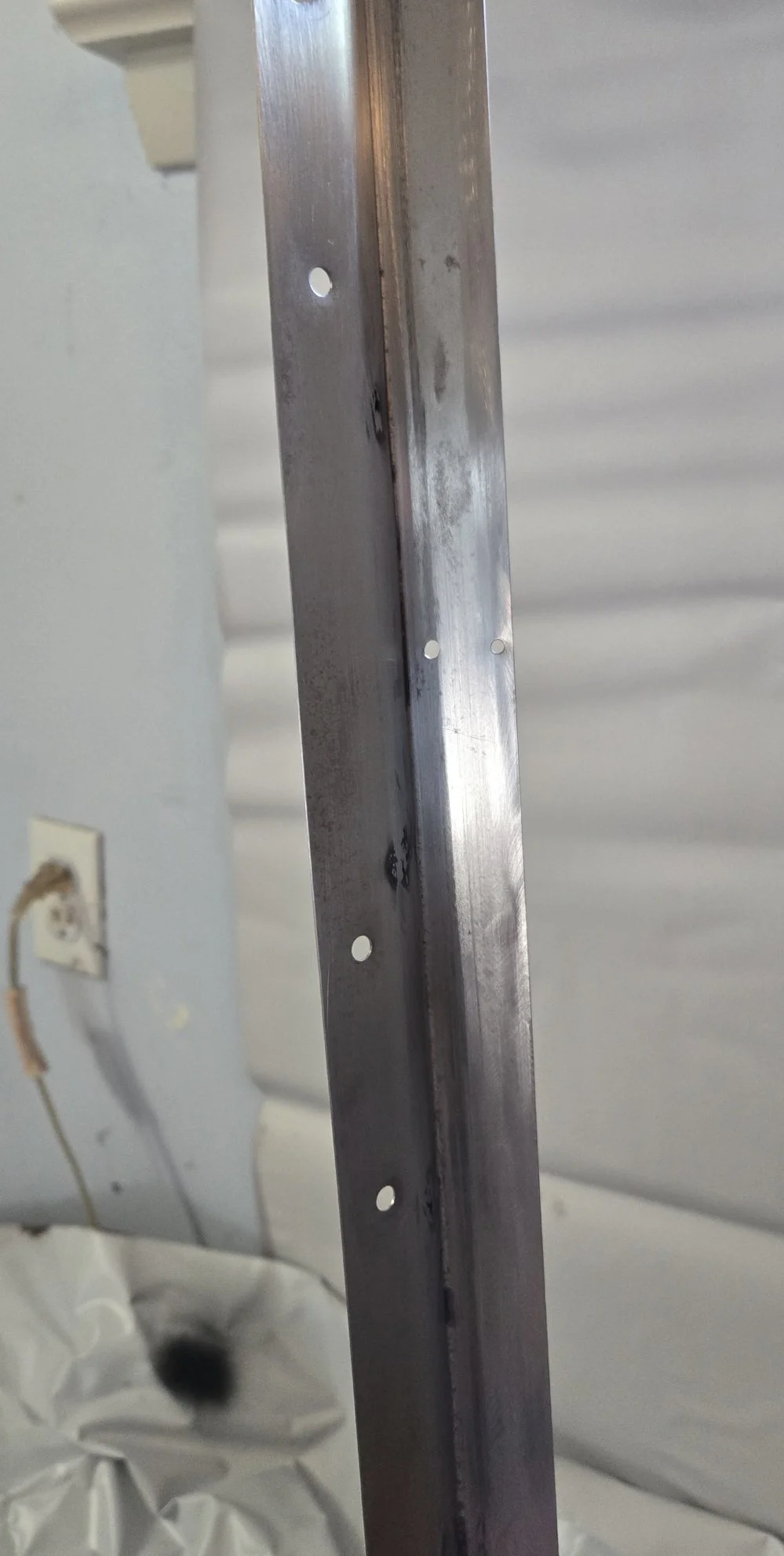
The bottom of the controller body has 6 threaded holes (M3 x .5 —10mm max depth!) which may have been for assembly/fixturing, so I imagined that whatever plate/slide/brackets/etc. I ended up with, I would attach to those and have a great bond end-to-end for the whole length of the controller.

I contemplated three brackets, bent from sheet metal, maybe riveted to a strip of aluminum strap stock that had elongated slots cut in it and some shoulder bolts for it to slide the 25 mm left-to-right etc. I thought and overthought for a few months, still unsure about the scale card itself and how to make it. I checked out various etching machines, 3D printers, etc. I almost settled for a $500+ machine that could precisely etch (via a stylus) into mild steel in small pieces, and then I might join the pieces together somehow keeping them straight and—
then it hit me!
Those name and sign placards we see in institutions, you know— they’re usually a dark face with white vinyl underneath that has been etched away to create the letters. I had seen some of those pretty long, like maybe 14-18” (35 - 45 cm). I thought perhaps I could get some of that stuff and etch it myself, or, better yet, find someone who would accept a CAD drawing or something with the exact pattern I needed, and maybe I could join two shorter ones together to make that 19.5” (50 cm) total.
After a fairly exhaustive online search, I found a company (hittmarking.com — not sponsored) that would accept my uploaded image file and print a vinyl placard from it— up to 20” in length!!
They also sold (seemingly only in tiny lengths) the aluminum channel that was made to accept this signage. Sliding scale issue solved too!!
I created a PNG file of what I wanted, uploaded, paid (about $50 USD with shipping/taxes/etc.) and waited about 12 days.
It arrived and I was completely happy with the quality and viability of the whole thing. This single purchase (far less than the $500+ I was planning on spending to do all of this myself, and no doubt do it much crappier) immediately brought the whole project to what felt like 75% completion.

Side-to-side, the scale drifted a few millimeters from drawing to engraving, but not nearly enough to be an issue— maybe a less than quarter tone longer overall.

I have a (flux core) welder, and I have a crappy sheet metal brake, so I came up with an idea for a bracket system. I would need to make it fit precisely and I wanted it to be as minimalist as possible in terms of appearance.
I got some 22 ga. sheet steel and set to work measuring the controller body’s major dimensions.


The base needed to be about 1 1/16” (27 mm) and the back needed to be around 5/8” (16 mm).
I did some layout on the sheet metal and added about 1/8” (3mm) between the base and back to account for the material eaten up by the brake bend in a later step.


Even though this is only 22 ga., I like using a cutoff wheel rather than tinsnips, because the wheel doesn’t curl or serrate the edge and it can (with your help) cut respectably straight lines even in very thin stock. I use snips if I want speed and don’t mind ‘lettuce’ edges and curling instead of neat, straight lines, like when roughing-in flashing or ductwork or something.

Possibly the cheapest sheet metal brake ever.
But it can be made to work.

And after lots of careful setup and tapping/adjusting, I got a respectable 90 degree bend along the whole thing.
Even crappy tools can produce usable results if you take lots of time to set up before the operation. Expensive stuff usually means easier/faster setup, so that’s the main tradeoff in my experience. Since I’m not a production shop making more than this single device, I can afford to take my time.
It was close to 10 minutes for this one bend in this one piece— that may sound excessive, but I only had 1 shot to get this right or otherwise end up scrapping the part and starting over. When you aren’t very good at things, being in any kind of a hurry can really stack the odds against you achieving even minimum acceptable results.

The design I had in mind was this 90-degree footplate and backer and then a top piece with a 25-degree back-rake from vertical. The sheet metal brake I have does not permit these kinds of bends so close to one another on the same piece, so I knew I was going to have to make this in two pieces and then attach them to one another.
For the back piece, I used tape to mark the cut layout for better visibility and even more accurate cuts (I learned this from Puddin’s Fab Shop on Youtube. Excellent channel and an excellent metal-fab tip!)


With the other half cut and marked, I had another careful session with the brake and got about a 25-degree bend right where I wanted it. I then drilled some holes to attempt to plug weld the sheet metal pieces together. In retrospect, my assumption that a 1/4” (6.5 mm) hole would give me lots of surface for welding was giving my flux-core welder way too much credit, so if I had to weld 22 ga. sheet metal with it again, I’d get a bottle of gas (my welder can do flux and MIG) and use the MIG process instead as it seems better-able to weld very thin stock.
I practiced about 20 welds on scrap before I got a technique that bonded the sheets without burning through them. That technique was to use the lowest power, almost the lowest wire speed, and moving the tip almost as fast as I would if coloring-in a circle with a permanent marker— really fast motion for welding. But it worked. I didn’t burn through. I got penetration.

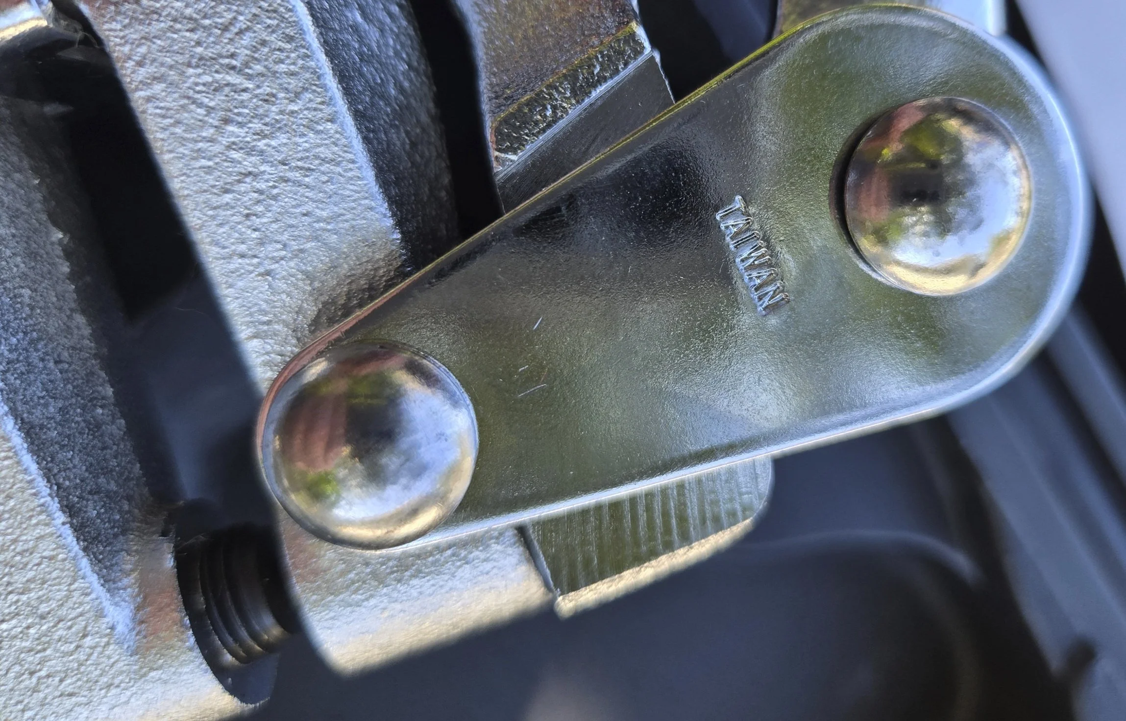
Flux can be an ugly process, but the penetration I got was pretty ideal all things considered. These pieces are solidly attached now, and with no rivets or screws or other space-taking nonsense. I inadvertently knocked this off the bench and also accidentally dropped it more than once and all of the welds held just fine, so plenty strong for what this piece will be doing.

I ground the faces of the welds to make them as flush as possible. These will never be seen once the unit is painted and assembled, but I wanted them to be some kind of uniform for easier sanding/painting later.

The unit will attach to the controller base via those 6 M3 screws, and marking the location of those threaded holes precisely will be important to getting everything to fit the way I’d like it to.
I contemplated making transfer screws by grinding points where the heads of the screws are, driving them in to a uniform depth, then then using those protruding points to mark the centers of the holes, but I suddenly got a better idea, an idea that would either be peak stupidity or momentary genius…

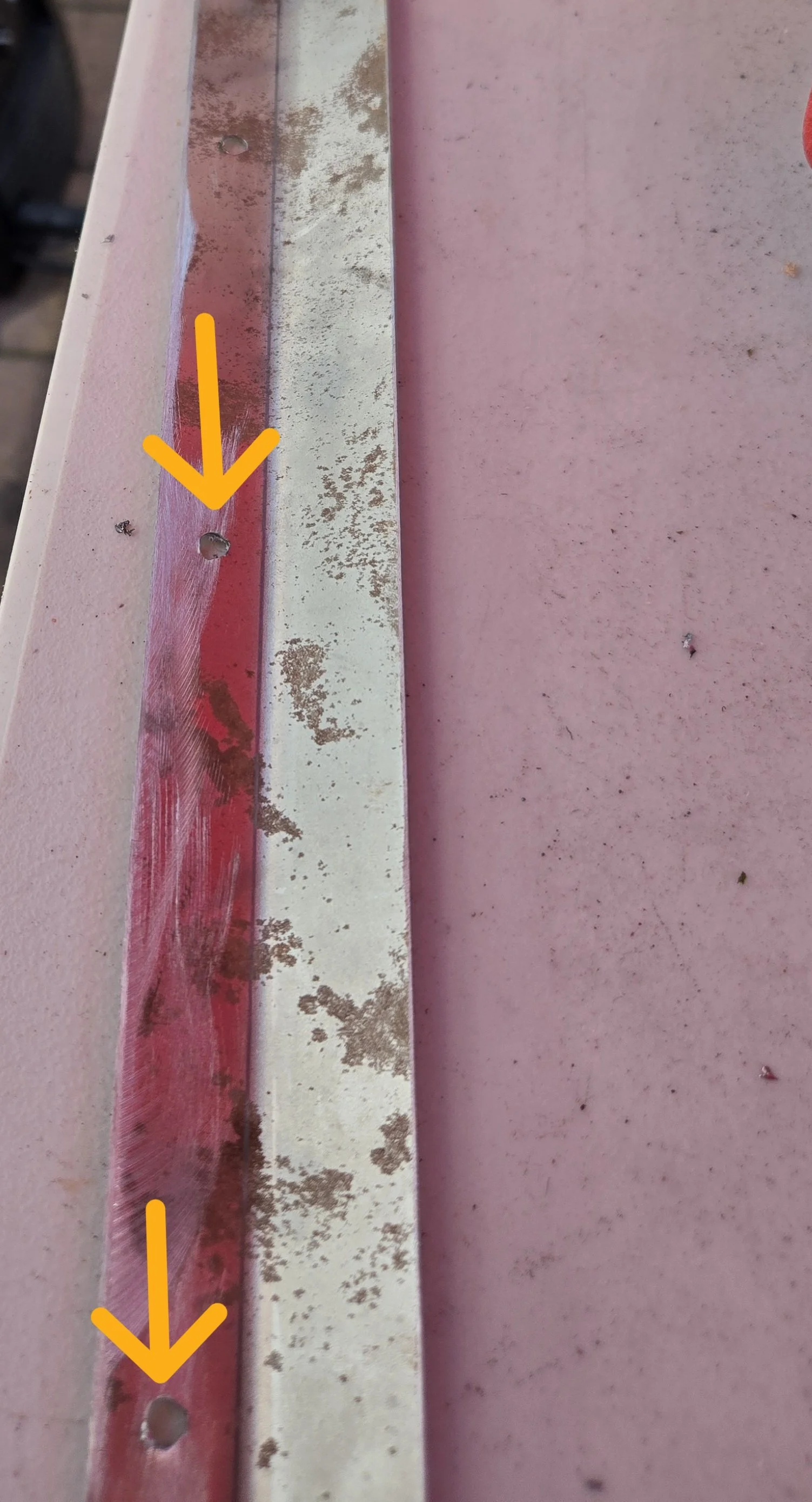
If I gingerly, straightly apply some of that thick, non-painter’s-type masking tape along the bottom of the unit…

Punch though the tape where the screw holes are to mark their exact locations relative to one another…

I can then carefully remove (so as not to stretch or deform) and transfer the tape to the bracket, using the reference edges to transfer all six locations in one (careful) simple step.

Maybe this will work? It looks promising.

I wanted neat holes, not egg-shaped gashes, and since this is sheet metal (22 ga.) I dug out my hand punch. It cost more than twice as much as units that appear identical, but it was made in a country known for much better quality tools, so I knew that cost difference was money well spent.

A spring-loaded center punch (Starrett knock-off from China, but still okay actually) and the eye-crometer will get the hand punch right into place.
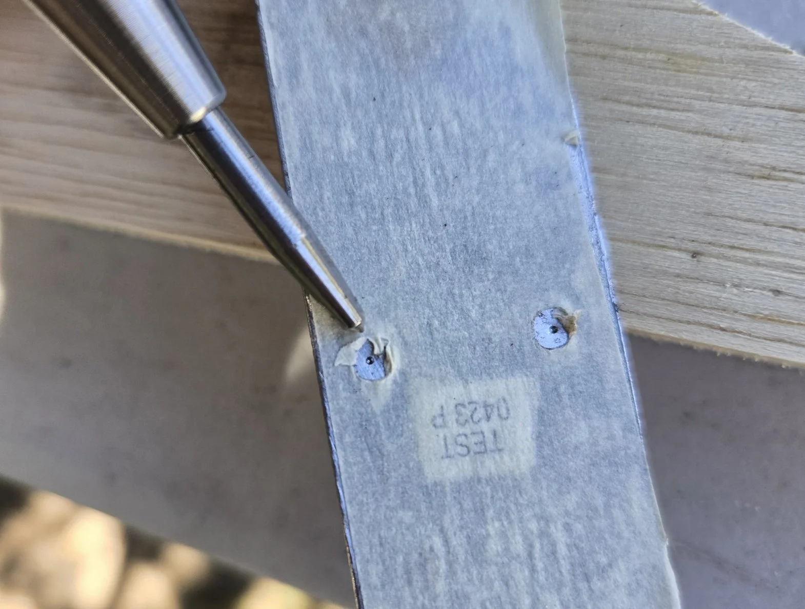
Punch and punch. No tear-out, no triangular holes, no shavings— just neat holes in the thin sheet metal.

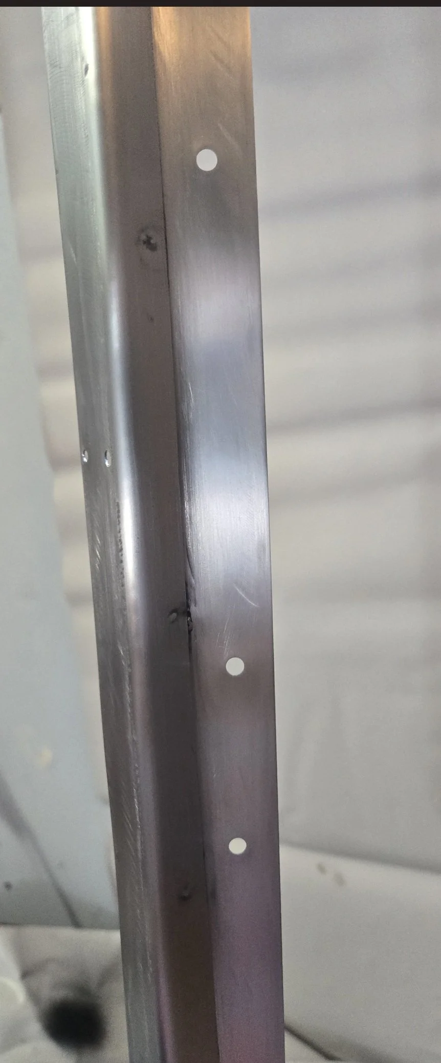
Peeking through the holes, hoping to find threads. Spot-on. I have the plate shifted a little for the sake of the photograph since the holes lined up exactly over the lightless voids (to my phone camera, at least) where the threads are and you would have no visual reference otherwise.


Yes indeed, the masking tape transfer trick worked. all 6 holes are within maybe .020” (0.5 mm)… close enough to get all screws started easily by hand.

It all lines up as I had hoped. Now to mark the mounting holes…

I wedged and propped various scraps to hold the aluminum pieces close to where they belonged as I marked the mounting holes based on the predrilled ones. I am very, very glad I did it this way as opposed to measuring and marking those holes and I’ll show why when we get to assembly. I was just being lazy, but it turns out, it was a very smart corner to have cut.


All of the holes are punched. It’s time to prep and paint.

120, 220, 320, and then maroon Scotchbrite took off 99% of the rust and other crap from the surface of the metal.
I wiped it down with a tack cloth and then naptha to get it super-clean before priming.
Two coats of red oxide primer, about a day apart. I could have coated and re-coated in like 20 mins, but in my experience, longer is better. As evidenced by my lack of skill and very makeshift paint facility, I’m not a production paint shop, so I have that luxury.

This is the first coat of texture paint. The surface finish definitely matters less when you use this stuff.

2 layers of the texture paint and about a week to fully cure have it looking pretty good for something no one will ever see.


The bracket is now mounted with M3 x 8 mm screws as planned. It cinched up well to a solid fit.

The drilling of the predrilled holes in the sign plates seemed random— about as good as I could’ve done myself, to be fair. I had to flip and swap a few times to get them to line up with the mounting holes I had marked and punched. I should have numbered the plates to avoid this, but with only 2 full sized it was an easy, iterative process to get them in the right places and directions.

First one mounted. I used M4 countersunk screws and KEPS nuts so the pieces could ‘float’ a bit before I locked them in place.

Final assembly almost complete. Notice that the bracket is now invisible.


Together for the final time— It’s DONE!

Here it is in its home location. It’s easy to play chords with my left hand on the keys and then play a melody on the Trautonium with my right.

Now, I can hit a C as quickly and accurately on the Trautonium as I can on the keybed below…

With that said, as I mentioned at the top of the article, there is a section of my Trautonium manual that is not quite linear relative to the rest, so for the 2nd of the 4 octaves, I need to finger just a bit sharp in order to be in pitch, but the other 3 octaves are all very in-tune with one another. This may be a peculiarity of my controller or of my controller interface. I’ll put it on the scope some day and see if I can isolate whether it’s a Sensofoil issue, a Doepfer issue, or a random conglomeration of analog domain factors. It’s still a very useful, playable instrument regardless of this 11 cm of minor inconsistency relative to the rest.
To keep it from shifting while playing (although it’s very heavy and tends to stay at rest) I added some self-adhesive rubber non-skid stuff. Mine came in sheets and I used a paper cutter to quickly get some perfect rectangles.

I spaced-out what I had to skip the screw locations and still provide plenty of contact area beneath the unit.

It doesn’t move at all. Maybe if I really got raucous like Keith Emerson or someone it might shift a little, but for the way I use it, it seems more than adequate.

You can hear it in action during the first minute of this song:
This was a fun build as it forced me to do things I don’t normally do in order to get a better result. The biggest stretch for me was having to order the custom engraved part as I had to place a lot of trust in the process and the people at the other end. I’m very glad I did and I’m also thankful that it was a good experience as I have found in the past that custom/odd requests are usually met with less than stellar delivery. The engraved piece is the star of this stage— and it looks phenomenal.
Metalworking is much, much more expensive than woodworking in terms of tooling and materials, but the things you can make with metal can open a lot of otherwise closed doors and lead to ideas which would never have seemed feasible.
Finishing skills — sand, smooth, prep, paint, etc. are probably the most important, so it’s good to practice those as much as you can. No better way to learn than by doing, especially with finish work. Always stick to the process. Do not take shortcuts with finishing. A slightly crooked birdhouse with a nice finish will always look nicer than a geometrically perfect birdhouse with a poor finish. I guess that’s why our ancestors called it ‘finishing.’
Avoiding mistakes is extremely important, but mistakes are inevitable, so you’ll always need to be able to recover from them. Experience is how you strengthen that ability.
And also speaking of finishing, I need to carefully sand the ends of the vinyl slide so they’re square and smooth. It’s bothering me now that I see it every day. But it should be an easy issue to fix, but also easy to screw up since vinyl is way softer than even wood when it comes to filing and sanding. I’ll get to it when I’m in the mood. I have other projects (like making a home for my UBXa-D) going at the same time as this one, so it’s lower on the list.

A reminder: I’m an absolute hack when it comes to welding sheet metal, painting, etc. If I can do this, anyone else can totally do this better. This means you.
Get your projects done!